 |

|
| |
Tubular
Glockenspiel
Welcome to my page on Tubular Glockenspiels! It's designed for middle and high school science students who are interested in studying the physics of metallic tubing and chimes! On this page, you will find a short introduction on the glockenspiel; a description on how it produces sound; and a demonstration on how to apply physics principles to this instrument – this section is particularly relevant for Science Olympiad participants in the Sounds of Music event.
Glockenspiels and orchestra bells are found in musical ensembles throughout the world. They normally consist of steel bars that are fixed on a frame in the shape of the ancient Greek lyre. As a result, they are also known by the name "bell lyre." [15, pg. 348] In a effort to design a similar sounding instrument with readily available materials, the glockenspiel on this page will be made using Electrical Metallic Tubing (EMT) – a material that is also used to construct wind chimes. In terms of classification, glockenspiels, orchestra bells, and wind chimes are all considered idiophones according to the Sachs-Hornbostel system, or in orchestral terminology, are considered part of the percussion family of instruments.
What produces the sound when wind chimes resonate? Is it the air inside of a tube, or the tube itself? If so, how does it vibrate?
Metallic tubes produce sound when they vibrate. Unlike wind instruments, which produce sound by shaping a column of air inside of a tube, idiophones produce sound by vibrating the substance of the instrument itself – in this case, the metal tubing. In this section, we are going to focus on the properties of this tubing; in particular, the different ways that it vibrates, and how this vibration creates the sound we hear.
Vibrations come in Threes:
Metallic tubing has three
different vibrational modes that can be excited
– two of them are harmonic in
nature, while one is non-harmonic.
The torsional
and longitudinal modes of vibration are harmonic, however they are not excited
during playing. The only vibrational mode that is excited during playing
is the transverse mode, which is non-harmonic [1, pgs. 64-65]. Given this,
we can assert that a metallic tube will produce audible frequencies that are not
necessarily a clear and distinct pitch, and that its overtones will not conform
to the harmonic series. How Glockenspiels Work More about vibrational modes: The transverse vibrational
mode deforms the tube in an up and down motion, resembling a
sine or sinusoidal wave. Torsional vibrations are characterized by a twisting of
the tube in a diagonal or side-to-side motion. Finally, in the the longitudinal mode, the energy of the wave travels through the bar instead of having it
displace air, as with the transverse and torsional motions [1, pg. 65, Fig. 7.2].
Rather, the purest tone one might hear would be "two pitches
approximately 17.5 semitones apart" [6, pg. 162].
Strike that tube:
Upon being struck by a mallet, a metal tube vibrates in a transverse motion, as shown in the animation on the right. Unlike aerophones, the audible sound is not being produced by a vibrating column of air, but rather the deformation of the tube itself. When the tube is struck at the mid-point, it vibrates in a transverse wave in its fundamental mode. Because the ends are free, the tube vibrates with two nodal points and three antinodal points. The area where the mallet strikes the tube becomes an antinode along with the two ends. The antinodal points are the areas of greatest movement, and the nodal points are where no movement occurs. Therefore, nodal points are areas with an amplitude of vibration equal to zero [2, pg. 434]. These areas of no vibration, or nodes, are precisely where the supports for the glockenspiel are placed. By making contact with the tube at these points, the supports serve to dampen all other modes of vibration except the fundamental mode. As shown above, when the tube deforms up and down, a longitudinal wave is produced outside the tube in the surrounding air. When the tube bends upwards a compression is formed above the tube, and when it bends downward a rarefaction is formed above the tube. As a result of this vibration, longitudinal waves radiate outward in a circular fashion both above and below the tube.
Now that we understand how metallic tubes produce sound, let's continue by exploring four more areas: frequency, amplitude, wavelength, and harmonics.
Frequency:
Frequency is simply a mathematical representation of how low or high a pitch is, and is based on the rate at which waves vibrate [15, pg. 8]. It is measured in Hertz, or number of complete wave cycles per second, and is commonly abbreviated as Hz [18]. Since sound is produced on EMT by the vibrating tube itself, the amount of time it takes for one complete up and down transverse motion, will determine the tube's frequency. To see how frequency can be demonstrated with metallic tubing, start the video below.
|
Changing Frequency on Electrical Metallic Tubing (EMT) |
As discussed in the video above, the frequency of a tube can be derived by the following equation, with Lo being the original tube length [10]:
Lo / (Freq. Ratio) ^ 0.5
Once you select your tubing diameter (1/2-inch or 3/4-inch) the tuning of your instrument can now be accomplished by varying the length of each tube, if you know the frequency ratio – it’s like a mathematical equivalent to a musical interval. For example, the frequency ratio for a musical fourth would be 4/3, for a perfect fifth – 3/2, and for the octave – 2. Once the desired interval is determined, one simply takes the Lo and divides it by the square root of the frequency ratio [10]. This is true because frequency is equal to 1/L2.
|
Determining Frequency with EMT |
If we change the length of a tube, we also change its frequency. Simply put: shorter is higher, and longer is lower. But it's actually more precise than that. The frequency graphic on the right depict two tubes. The metallic tube on the left has a length that is equal to 1 unit, while the tube on the right is approximately 70 percent of that length. Notice, that the tube on the right is vibrating at twice the speed as the tube on the left, which is illustrated by the flashing red arrows that occur when the tubes complete a wave cycle. This demonstrates, according to the equation above, that an octave above a given frequency can be calculated by deriving roughly 70 percent of its length.
Let's complete this equation for an octave. If we make the original length 1, and remember that the frequency ratio for an octave is 2, the equation would be:
Lo / (Freq. Ratio) ^ 0.5
1 / (2) ^ 0.5
= 0.707 ~ 70.7 percent
Amplitude:
Amplitude is the variation or displacement of a wave from its mean value. With sound waves, it is the extent to which air particles are displaced, and is experienced as the intensity or loudness of a sound. As shown below, when a tuning fork vibrates to a greater degree, it displaces more air particles in each compression. When the tuning fork vibrates to a lesser degree, it displaces fewer air particles in each compression.
Amplitude can be changed on metallic tubing by varying the amount of striking force applied to the tube. If more force is applied, the tube deforms to a greater degree and displaces a larger number of air particles as it vibrates. If the tube is struck with less force, it deforms to a lesser degree and displaces fewer air particles with its movement. This is true because the tube moves up and down with lesser or greater deformation depending on the force that is applied to it. Striking softly, with less force, will produce less amplitude. Striking harder, with more force, will produce greater amplitude.
Another way to change the amplitude is to change the hardness or softness of the mallet. A harder mallet will cause most of the kinetic energy to be transferred. However, with a softer rubber mallet, more energy is transferred into elastic and dissipated energy, resulting in less movement. Therefore, soft mallets produce less amplitude, and hard mallets produce more amplitude.
|
Varying Amplitude |
 |
Wavelength:
|
Wavelength and Modes of a Glockenspiel |
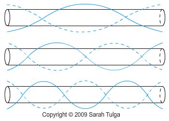 |
The first three vibrational modes of a metallic tube are shown on the left. Again, these transverse vibrations are non-harmonic, and therefore do not exhibit predictable frequency ratios, as would be the case with a vibrating column of air.
For the first mode, the nodal positions are at 0.224 x L, where L represents the total length of the tube. The wavelength of this mode would equal the exact length of the tube, as shown by the transverse wave that is superimposed on top of the tube.
The second mode of vibration would have a frequency ratio of 2.756, where the frequency ratio is fn/f1. The nodal points would be at 0.132 x L, 0.5 x L, and 0.868 x L, and the wavelength would be approximately 2/3rds of the length of the tube.
The third mode of vibration would have a wavelength that is roughly 1/2 of the length of the tube. The frequency ratio would be 5.404, and the nodal points would be at 0.094 x L, 0.356 x L, 0.644 x L, and 0.906 x L [2, pg. 433, Table 10.2].
To learn more about demonstrating these modes, please see the video below.
Nodal Points:
|
Nodal Points of the Fundamental Frequency |
 |
The nodal points for the first three modes of vibration are displayed in the wavelength graphic above.
These nodes are important reference points to consider when designing and constructing an instrument with EMT. Most importantly, are the nodal points for the fundamental mode, which produces the lowest resonant frequency that is possible for a given tube. As shown on the right, the nodal points for the fundamental mode are at 0.224 x L, where L is equal to the total length of the tube.
It is important that the supports for your glockenspiel be directly under these points – this also applies to holes that are drilled into chimes for hanging purposes. The first mode of vibration is not affected or dampened at these points, because these points are at nodal positions, which by definition have a vibrational amplitude equal to zero [2, pg. 434]. The second and third modes, as shown in the wavelength graphic above, have large vibrational amplitudes at these support points, and are consequentially silenced or dampened [2, pgs. 434-435]. By allowing a tube to freely resonate the fundamental mode, while dampening higher modes, the overall sound and pitch of the tube becomes more predictable. To learn more about testing these nodes, please see the video below.
Overtones and Timbre:
|
Demonstrating Nodes, Modes, and Overtones with EMT |
An important characteristic of idiophones, including metallic tubes, is that they produce overtones, but not harmonics. This is because the overtone frequencies they produce are not multiples of the fundamental frequency. Instead, their frequencies can be rather unpredictable and dissonant, which is why they are usually dampened, as explained in the Nodal Points section above [15, pgs. 10-11, 635].
However, if we want to demonstrate overtones on EMT, we need to consider two factors: the physical characteristics of our mallet, and the point at which we hold the tube.
Regarding mallets, the harder it is, the more it will produce faster higher overtones. The softer it is, the more it will produce slower vibrations like the fundamental mode. Because of this effect, our choice of mallets also changes timbre, or the quality or tonal color of the sound. With harder mallets, higher overtones are mixed into the composite sound, and with softer mallets, the lowest fundamental mode is predominant.
Regarding dampening, the point where you place your fingers becomes a nodal point, and serves to dampen all of the modes that vibrate in that spot. By selecting your nodal point carefully, you can dampen other modes of vibration, allowing the one you select to resonate predominantly. In so doing, you can demonstrate your knowledge of transverse vibrations, nodal points, and overtones, in a way that is both audible and verifiable. To learn more about how to demonstrate these principles, please see the video on the right.
Works Cited
[1] Neville H. Flectcher, Thomas D. Rossing, The Physics of Musical Instruments (Springer- Verlag, New York, 1991)
[2] Murray Campbell, Clive Greated, The Musicians Guide to Acoustics (Schirmer Books, New York, 1988)
[3] http://www.physicsclassroom.com/Class/sound/u11l3d.cfm
[4] http://www.phys.unsw.edu.au/jw/fluteacoustics.html
[5] http://www.phys.unsw.edu.au/jw/pipes.html - interaction between acoustic pressure and acoustic flow
[6] Donald E. Hall, Musical Acoustics (Brookes Cole, 2001)
[7] Alexander Wood M.A., D. Sc., The Physics of Music (Methuen & Co. Ltd., London)
[8] John R. Pierce, The Science of Musical Sound (W.H. Freeman and Company, New York NY, 1992)
[9] Thomas D. Rossing, The Science of Percussion Instruments (World Scientific Publishing Co., Singapore, 2000)
[10] http://www.phy.mtu.edu/~suits/windchime.html
[11] http://www.phy.mtu.edu/~suits/scales.html
[12] http://www.exo.net/~pauld/summer_institute/summer_day11sound/ringing%20_Al_rod.html
[13] http://wordnetweb.princeton.edu/perl/webwn?s=wavelength
[14] Robert Erickson, Sound Structure in Music (University of California Press, 1975)
[15] Willi Apel, The Harvard Dictionary of Music, Second Edition (The Belknap Press of Harvard University Press, Massachusetts, 1972)
[16] http://www.physicsclassroom.com/Class/sound/U11L3c.html
[17] http://www.windows.ucar.edu/tour/link=/earth/Atmosphere/tornado/beat.html
[18] http://science.education.nih.gov/supplements/nih3/Hearing/other/glossary.htm
[19] http://www.phys.unsw.edu.au/jw/didjeridu.html#work
[20] http://www.phys.unsw.edu.au/jw/brassacoustics.html
[21] http://www.panflutejedi.com/pan-flute-history-main.html
Copyright © 2009 Sarah Tulga